Cassette Lockring Removal Tool
Analysis

Standard Wrench
Standard Lock Ring Tool
RADD
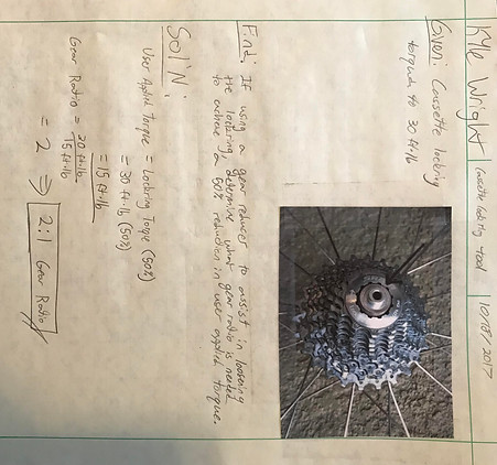
Requirement – Device must reduce user torque input by 50%
Analysis – A standard bicycle cassette lock ring is torqued to 30 ft.lb. A 50% reduction of this torque is equal to 15 ft.lb. The ratio between the two torque values is 2:1
Design – A 32 tooth gear and 16 tooth pinion gear were selected for the application. This produces the exact same 2:1 ratio required through the calculations.
Documentation – Calculations for the analysis are located in Appendix A1.1 of the report or the "Required Gear Ratio" image below.
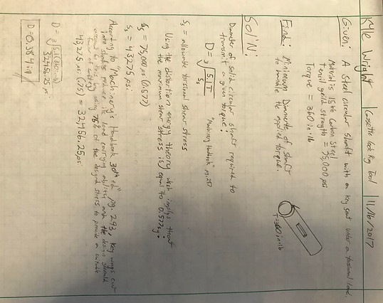
Requirement – 1566 carbon steel gear shaft with a key seat must withstand a torque of 30 ft.lb.
Analysis – Finding the minimum diameter of the shaft for this scenario will provide a benchmark of the smallest size to be used in the design. The material yield strength is 75000 psi but this value is reduced due to the shear stress experienced during torsion. This value is then further reduced due to the stress concentration of the key seat. The allowable shear stress factor applied to the yield strength is 0.577 due to the distortion energy theory. This shear stress is then reduced by 25% to accommodate for the key seat according to the “Machinery’s Handbook 30th ed”. In the end the design stress is now 43275 psi from the original 75000 psi. Using the equation for Diameter of a solid circular shaft required to transmit a given torque the minimum diameter can now be calculated.
Design – The calculations revealed the benchmark for the smallest shaft diameter to support the 30 ft.lb. torque was 0.384in. The smallest diameter on the gear shaft for the design is 0.480in which is 25% over the benchmark.
Documentation – Full calculations for the analysis can be found in Appendix A1.4 or in the "Minimum Shaft Diameter" image below.
Requirement - 3 pins of a fixed size must be made of a material that can sustain a direct shear force
Analysis - The area of the pin is 0.078in2 and the total force spread between the 3 pins is calculated to be 406.32lb. Solving for the shear stress divided by the 3 pins is 1736.41psi/pin.
Design - From the analysis calculations it was determined a material with a shear strength greater than 1736psi would be suitable for the application. 1020 steel was selected with a shear strength of 30480psi which produces a safety factor of over 17. This is more than necessary but the material is readily available and has good manufacturability.
Documentation - The full break down of the calculations can be found in Appendix A1.7 of the report.
Further Analysis of Device
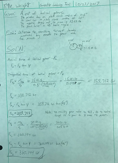
Axial Force (Thrust Load)
Helical gears produce an axial force which requires some type of bearing, shoulder, or other means of supporting this force. In the "Axial (Thrust) Force" image below or Appendix A1.2 of the report an analysis is performed to determine the axial force produced by the gear set selected for the device. These thrust loads can then be used to determine what kind of thrust bearings are suitable for the application.
Radial Load
When under load, a gear set will produce a radial force that acts perpendicular to the axis of rotation and opposite of the other gear. Appendix A1.3 of the report provides the calculations for this force.
Minimum Key Length
One key per gear is used to fix the gears to the shafts and transmit the torque. The key way built into the gears being used is 0.500 inches in length and a key the entire length of the key way is utilized. Calculations determining the safety factor of this design are shown in Appendix A1.5 of the report.
Shaft Key Seat Depth
Key seats are machined into the gear shafts and the optimal depth of the key seat needed to be determined. In Appendix A1.6 of the report the calculations for these key seats are shown.
Gear and Pinion Shaft Stress and Deflection
The radial force produced by the gear set subjects the gear shafts to stresses and deflections similar to that of a loaded beam. Appendix A1.8 of the report shows the calculations of the stress and deflection experienced by the gear shafts due to the radial loads.
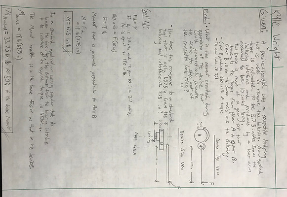
Moment Created During Device Use
The device will require a lever arm to help the user produce the initial torque input to the pinon shaft. Due to the device having an overall thickness greater than a traditional wrench and lock ring tool setup (example shown in Image A.1), the applied force by the user is great enough that a moment is generated that causes a tendency for the device to rotate perpendicular to the rotating axis of the lock ring. This moment does have an effect on the stability of the device when engaged into the cassette and lock ring. A similar scenario is when a ratchet with a long extension, say 5 inches or greater is used to loosen or tighten a bolt. Without any support of the tool close to the bolt, the socket will try to “cam off” of the bolt head. Appendix A1.9 of the report or the "Moment Created During Device Use" image below provides calculations representing this possible unstable scenario when using the device.
Cog Holding Plate Locating Bolts Shear Stress
A plate holds the pins that contact and grip the 11 tooth cog that ultimately holds the cassette in place. This plate can slide up and down the rotating axis of the gear shaft via shoulder bolts. These bolts must withstand the force of the tool wanting to rotate when the lock ring is being loosened. Appendix A1.10 of the report provides the calculations for the shear stress that one bolt would experience if it was the only bolt preventing the rotation.
Potential Lever Arm Deflection
The current modeled and design of the device does not utilize a built in lever arm. However, if the need arises for the integrated lever Appendix A1.11 of the report shows calculations predicting the deflection of a possible lever arm design that would utilize any leftover materials.
Shear Stress on Assembly Plate Screws
The screws that hold down the assembly fixing plates are subjected to shear forces produced by the helical gear set’s thrusts loads. Appendix A1.12 of the report presents the calculations of the shear stress in direct shear that one of the screws is subjected too and makes any future changes to screw material simpler by establishing the magnitude of the stress experienced.
Minimum Shaft Diameter
Required Gear Ratio
Axial (Thrust) Force