Cassette Lockring Removal Tool
Construction

Methods & Construction
Other than the initial vision of this project, the analysis and design was carried out at the CWU campus. The device is a collaboration of pre manufactured components and parts machined on the CWU campus. Pre-manufactured parts were purchased from various vendors and were typically of complex geometries or assemblies. A list of the parts can be found in Appendix C1.1 of the report. Parts made on the CWU campus were made from raw materials or modifications of previously existing components.
Assembly
The main parts purchased from suppliers are the two helical gears, thrust bearing assemblies, open ball bearing assemblies, keys, and external retaining rings. Components that are made on campus are the two gear shafts, top and bottom bearing carrier plates, cog holding plate assembly, and modifications to a previously existing cassette locking tool. Manufacturing will be completed in a specific order. First, the bearing carrier plates will be machined and the open ball bearings will be press fit into their respective holes on the plate. Second, the gear shafts will be turned and milled to achieve the appropriate features. Third, the thrust bearings, helical gears, bearing carrier, and gear shafts will be assembled together and secured by external retaining rings. A visual tree diagram of the main assemblies can be seen in Appendix C1.2 of the report.
Engineering Disciplines/Relevant Equations
Engineering discipline areas of interest for the project include statics, strength of materials, and machine design in general. Equations used multiple times for the design and analysis are Direct Shear , Torque , and Diameter of Shaft for Given Torque . These and other related equations were used to help optimize design parameters of several components of the device including bolt sizes, minimum shaft diameters, and appropriate gear ratios.
Manufacturing
Manual machining on a lathe and mill along with CNC machining were used to produce essentially all of the parts that were not purchased. Below are images and videos of some of these parts during and after manufacturing.
Manufacturing Issues/Modifications
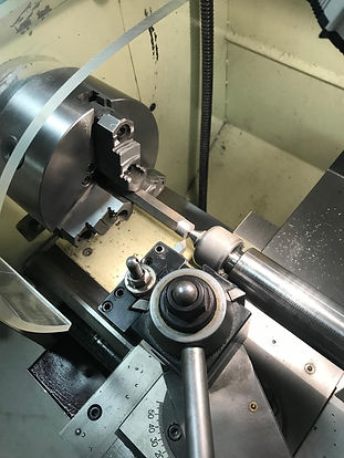
During manufacturing, multiple issues were discovered and presented their own challenges. The first issue to arise was holding of the different work pieces in the lathe. All of the cylindrical parts in the device are rather small and do not leave much room for secure and accurate clamping of the work piece as well as room for the machine tool. Improved process and procedures help alleviate this issue by leaving the material stock full size and machining the part completely then cutting it off the stock material. This provided lots of stock material for work holding and would leave plenty of material accessible for machining. Image 3.1 displays the improved work holding setup.
Another issue was the change in material hardness of the modified cassette tool after it had been welded to the gear shaft. The material became very hard and the turning tools had much difficulty when machining light cuts. The tool tip would simply break or chatter against the material and create uneven rough looking cuts. Unfortunately there was no way to fix the hardness problem in a timely fashion so the rough finish would remain but it has no effect on the overall function of the device. During the welding process, there was a slight overlap of weld splatter that effected the key seat machined into the shaft. Once again, this is something that should have been done last instead of earlier in the manufacturing process
Tolerances for the press fit application of the bearings in the top and bottom bearing carriers was certainly a learning experience. The relative light load demands and almost non-existent speeds during the use of the device made it clear that even with matching diameters, the bearings and bores for the bearings would have been a plenty tight fit. Instead, the bearing carriers were machined to be 0.001” undersize of the bearing outer diameter. This made installation of the bearings more difficult than originally thought. Even with heating of the bearing carrier and cooling the bearings, the fit was still rather tight and would make any future removal of the bearings difficult.
When final assembly of the device was done it was apparent that the spacing between the bearing carriers was slightly smaller than what was needed to fit the shaft assemblies set of thrust washers, bearings, and the gear all in-between the two bearing carriers. Luckily the thrust washer assemblies each use two washers that are only 0.032” thick each. Removing one washer from one thrust assembly per shaft remedied the clearance issue.


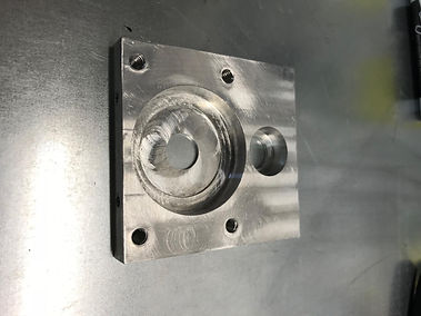
Top Bearing Carrier
Top Bearing Carrier Machining
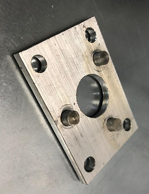
Bottom Bearing Carrier
Cog Holding Plate
Cog Holding Plate Machining

Pinon Shaft
Pinon Shaft Machining

Disassembled Device
Device Operation
Operation of the cassette lock ring tool device requires completion of a short sequence of tasks. First, the cassette lock ring socket needs to be placed into the cassette lock ring while keeping the cog holding plate and its pins from touching the cassette. Second, index the cog holding plate’s 3 pins in-between teeth on the 11 tooth cassette cog (the first and smallest cog on the cassette). The cog holding plate can side up and down in relation to the bottom of the device body along with rotating the body of the device to help align the pins. It is essential that the cassette lock ring socket and cog holding plate pins are both nested into their respective positions before proceeding to the next step. With one hand hold and stabilize the outer diameter of the wheel and with the other hand use a 16mm socket on a breaker bar or ratchet wrench to turn the pinion shaft on the top side of the tool in a clockwise direction. The device body which is now fixed in place to the cassette should not move due to the cassettes inability to rotate clockwise in relation to the rest of the wheel being stationary. It is at this time that the clockwise rotation of the pinon shaft will rotate the gear shaft in the counter clockwise direction. The cassette lock ring socket is fixed to the end of the gear shaft and will loosen the cassette lock ring.
Benchmark Comparison
This device is unique in its approach to performing its task compared to all other traditional methods. There is also no available ratings or previously quantified performances associated to other procedures. The amount of force to loosen the cassette lock ring disregarding lever length is the main aspect that can be improved and benchmarked against other methods without post design testing for comparison. For these reasons the focus of the design was based on not only reducing user effort but also improving the ergonomics of the task and overall time to complete the task.
Performance Predictions
- The force that the user will have to input to loosen the lock ring is estimated to be 50% of what is currently the standard.
- The time to perform the entire task of loosening and removing the cassette lock ring cannot be accurately calculated but based on the device design it is estimated that the task will take at the worst 100% the time as other methods and could potentially be far faster based on user familiarity with other methods.
- The ergonomic performance of the device again cannot be calculated before testing but it is highly possible considering the issues and difficulties associated with traditional tools and methods that the device will receive high remarks from testers of its ease of use.
Early Sketch of Device

A a torque multiplier or gear box with a "locking arm" to stabilize the device on the cassette when in use.